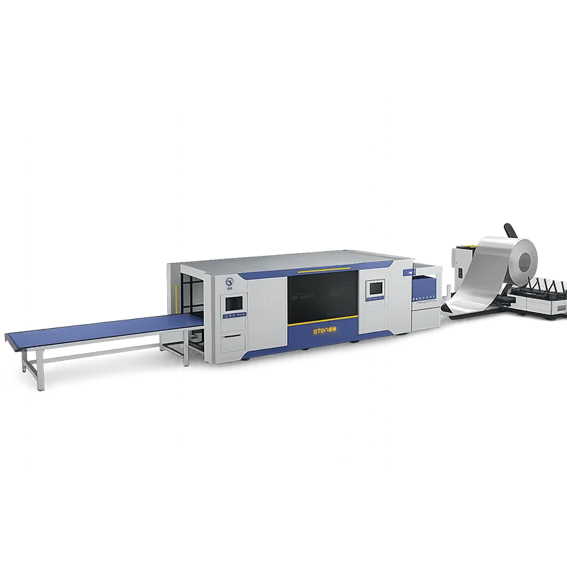
A coil fed laser cutting system uncoils, levels, feeds and laser-cuts strip in one continuous line instead of loading pre-cut sheets. STON‘s line runs 0.5–2.0 mm material, 200–1500 mm coil width, coils up to 10 T, at 0–12 m/min. Below are the full published figures and the yield math.
What sits inside the line, module by module
The line is a chain, and every module in it constrains the one after it:
- Uncoiler — unwinds the strip coil and holds a synchronous material balance with the leveler. Body and base are welded structures given heat aging treatment.
- Leveler — pulls out coil set and residual stress so the strip presents flat to the laser. Leveling rollers are 40Cr; work-roller bearings are self-aligning or needle roller type. Roll configuration is specified against your thickness range and flatness target rather than fixed.
- Servo feed — high-precision ground rack drive with servo control, holding position at speed so the cutting head is working against a known datum.
- Fiber laser cutting unit — power selected from the 1–6 kW range, with a process-parameter database in the CNC and real-time parameter adjustment during the cut.
- Water cooling — two circuits cooling two core locations independently, with digital chiller temperature display and automatic start/stop against setpoint.
- Hydraulic and pneumatic station — one integrated pump station feeding the cylinders, with relief valves, gauges, regulating valves, check valves and solenoids.
- Unloading / stacking — configured to the blank size and downstream process.
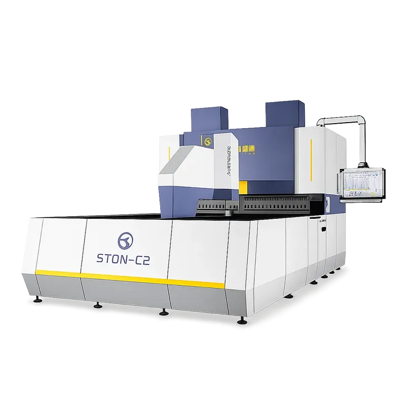
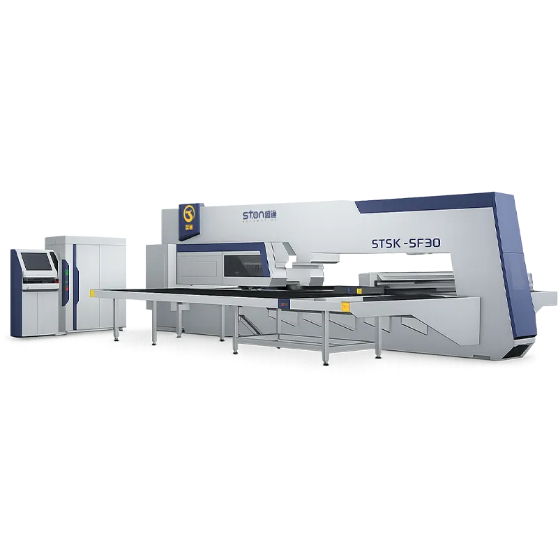
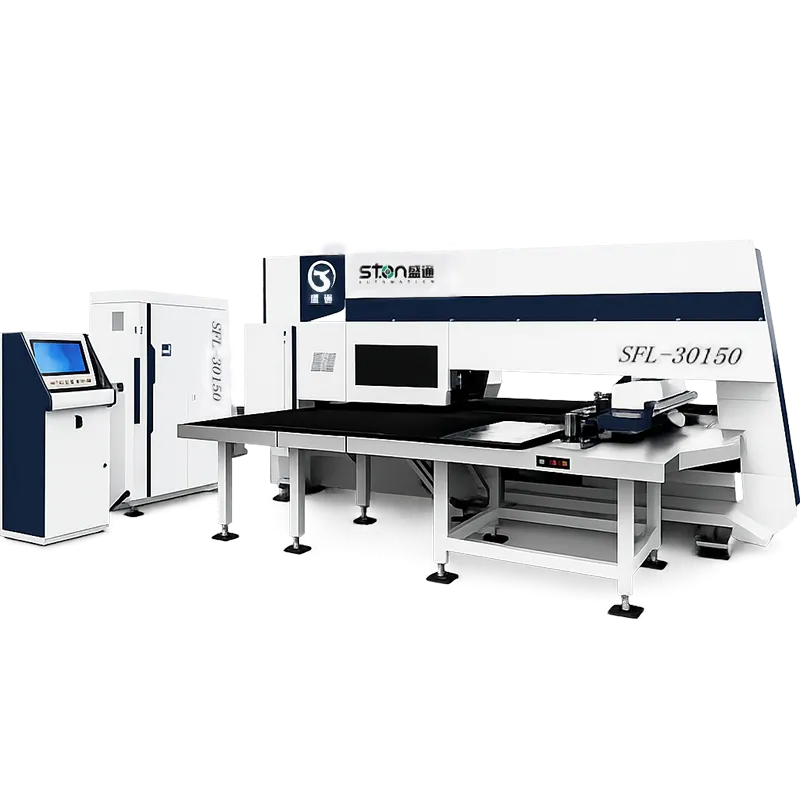
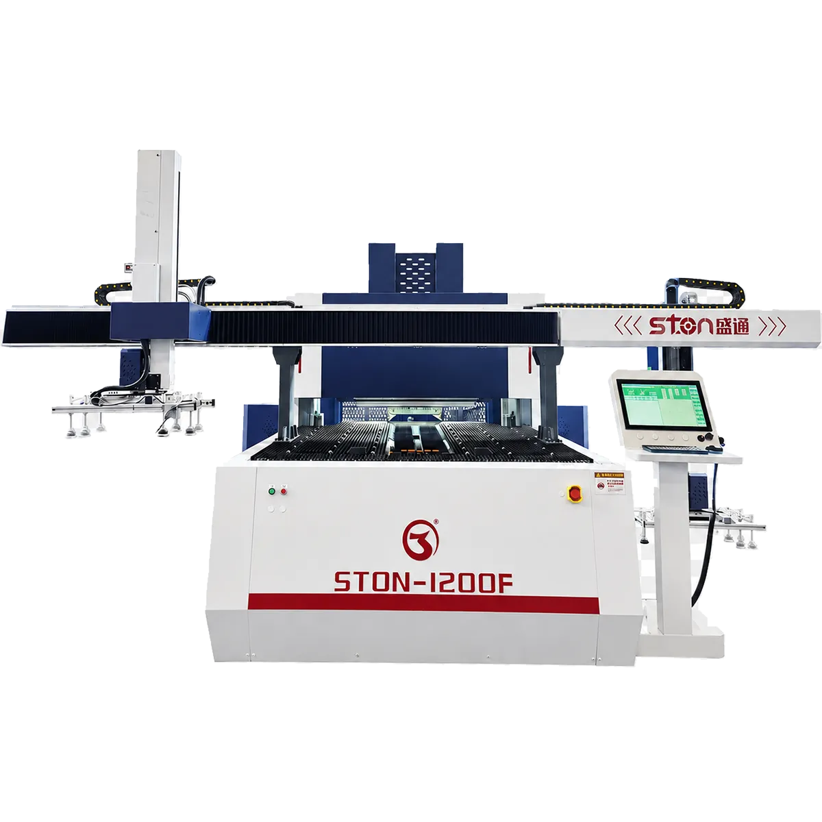
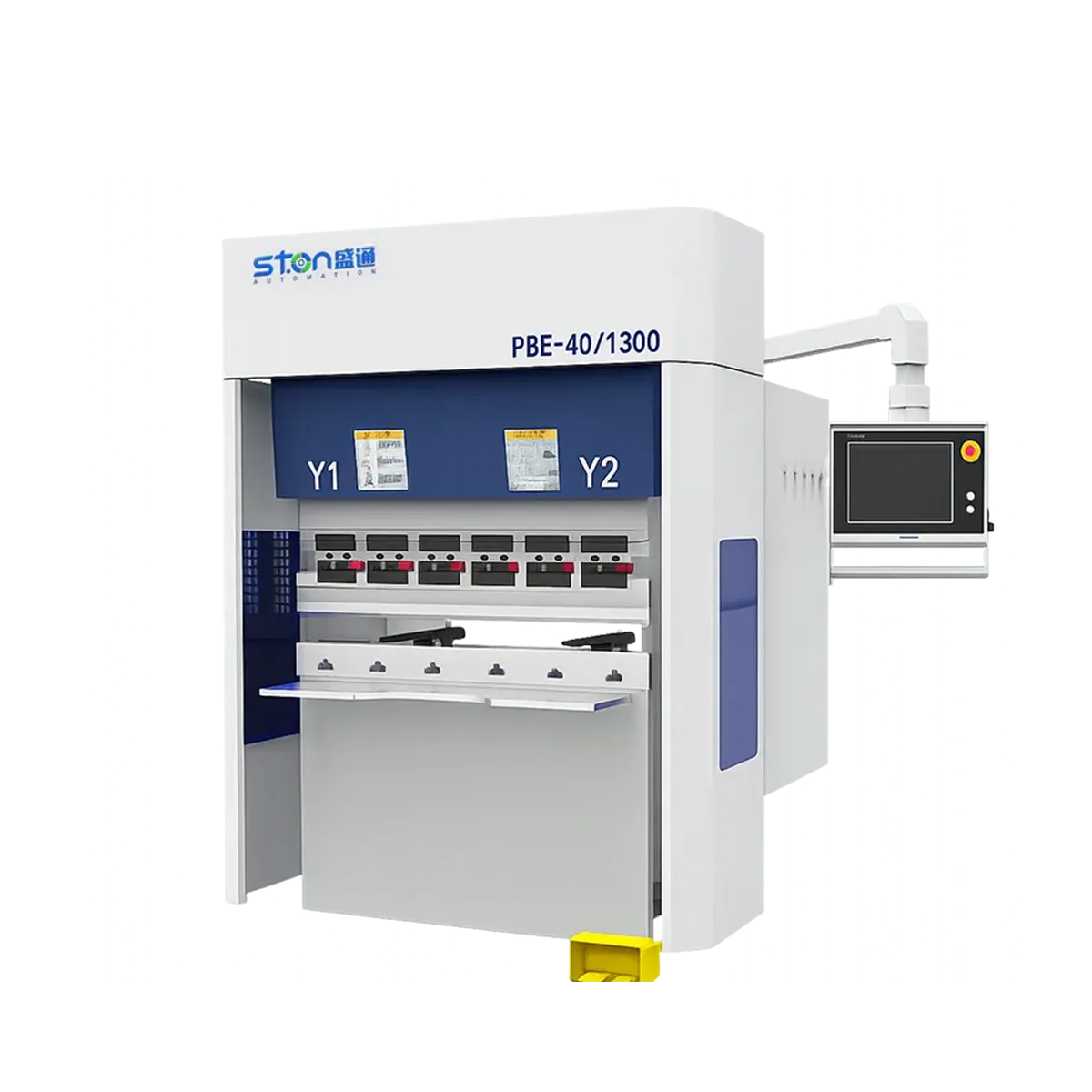
Where the line continues past blanking, the same control system carries the strip into CNC turret punching, panel bending and, in the fullest configuration, a robot welding station. That matters for the ROI case later on: the material saving is available on day one, but the labour saving only lands when the blank stops being handled manually between stations.

Coil geometry your supplier has to match
Before the machine question, there is a procurement question. A coil fed line is only as flexible as the widths your steel supplier will slit for you, and slit-to-width coil usually carries a longer lead time than standard cut-to-length sheet.
Four things to settle with the mill or service centre:
- Available slit widths and the minimum order quantity at each — the utilisation gain in the next section depends almost entirely on this.
- Inner diameter, which must sit inside the mandrel range (Ø470–630 mm / Ø508–630 mm depending on build).
- Outer diameter against Ø1000–1600 mm, and weight against the ≤10 T ceiling.
- Oil film and surface condition, since heavy oiling changes both leveling behaviour and cut quality on thin galvanized.
One arithmetic check worth running before you commit: a 10 T coil of 1.0 mm material at 1250 mm width carries roughly 1,019 m of strip (1.25 m × 1.0 mm × 7.85 g/cm³ ≈ 9.81 kg per running metre). That number tells you how often an operator and a crane are needed, which is the real staffing input, not the line speed figure.
The yield math: two nesting scenarios, one spreadsheet
This is the section competitors leave out, and it is the only one that decides whether the investment works.
Utilisation on a sheet-fed laser is capped by the sheet format. Utilisation on a coil line is capped by the strip width, with length effectively continuous. The size of the gain therefore depends on one thing: how badly your parts nest into a standard sheet.
Assumptions used below (substitute your own — these are worked illustrations, not measured plant data): 10 mm edge margin, 5 mm web between parts, standard sheet 1250 × 2500 mm, 1.0 mm galvanized at 7.85 kg/m², material at USD 1,200/tonne, 200,000 parts per year.
| Comparison Item |
Scenario A: Part Nests Well (400 × 300 mm) |
Scenario B: Part Nests Badly (460 × 340 mm) |
| Sheet-Fed: Parts per 1250 × 2500 mm Sheet |
24 (3 across × 8 down) |
14 (2 across × 7 down) |
| Sheet-Fed Utilisation |
92.2% |
70.1% |
| Selected Coil Width |
1250 mm |
950 mm (slit to suit) |
| Coil-Fed Layout |
3 across, 305 mm pitch |
2 across, 345 mm pitch |
| Coil-Fed Utilisation |
94.4% |
95.4% |
| Input Material per Part |
0.1302 → 0.1271 m² |
0.2230 → 0.1639 m² |
| Material Saved per Part |
0.024 kg |
0.464 kg |
| Annual Material Savings at 200,000 Parts |
≈ USD 5,900 |
≈ USD 111,000 |
Nineteen times the return, same machine, same year, different part geometry. Scenario A does not justify a coil line on material savings alone; it has to be justified on labour, handling damage and throughput. Scenario B pays for a substantial part of the line inside two to three years on scrap reduction by itself.
Two further line items belong in your model, and I am not going to invent numbers for either. Coil stock is normally bought at a lower price per tonne than cut-to-length sheet — get both quotations from your own supplier rather than accepting an industry average. And coil occupies less floor area per tonne than palletised sheet, which is worth costing if your warehouse is the constraint.

How this compares with standalone sheet-fed cutting cells
Against the general category of standalone sheet-fed laser cells that most fabrication plants already operate, the coil line trades flexibility for yield and continuity. The sheet-fed cell wins on material and thickness variety and on independent failure. The coil line wins on utilisation for a repeating part family, on the elimination of sheet handling between store and machine, and on unattended running between coil changes.
Against die-based blanking presses, the comparison is different again: no die design, purchase or maintenance cost, and part geometry changes are a programming task rather than a tooling project. The trade is cycle time on very high-volume, single-geometry runs, where a press still wins.
Because the line is fully enclosed and interlocked, the safety case is built to CE requirements under Machinery Directive 2006/42/EC, with risk assessment following EN ISO 12100 — the documentation an EU importer will ask for before the line is energised, so raise it during technical clarification rather than at shipment.
What it costs, and why there’s no list price
STON does not publish a price range for this line, and I am not going to invent one. Quotation is required, because the price of a coil fed laser cutting system is not a model number — it is a configuration.
The variables that move it most:
- Laser power selected within the 1–6 kW range
- Coil width and weight class, which size the uncoiler, leveler and coil car
- Single- versus dual-head cutting, and single versus dual uncoiling
- Leveler roll configuration against your thickness and flatness target
- Whether the line stops at blanking or continues into turret punching, panel bending and welding
- Unloading and stacking design, which follows blank size and weight
- Destination-specific electrical, safety and documentation requirements
Send part drawings, material and thickness range, annual volume and a plant layout, and the configuration comes back defined rather than approximated.
Site and utility requirements before the crate arrives
Confirm these against your building, not against the brochure: three-phase 400 V ±5% at 50 Hz ±2%; compressed air at 0.5–0.6 MPa delivering 0.6 m³/min; running height +800 mm; crane capacity above 10 T; and a clear floor run sized to the configuration, which grows substantially once punching and bending are added inline.
An eight-step evaluation sequence
- Pull your five highest-volume part footprints and calculate nested utilisation on your current sheet format, using your real edge margin and web values.
- Recalculate the same parts against two or three candidate coil widths.
- Get quotations from your steel supplier for both coil at those widths and cut-to-length sheet, per tonne.
- Check every part in the family against the 0.5–2.0 mm envelope, and against 1.5 mm if any of it is stainless.
- Verify crane capacity and confirm your coil ID and OD sit inside the mandrel range.
- Measure available floor run and confirm +800 mm working height against downstream equipment.
- Confirm power and compressed air supply against the figures above.
- Send a sample coil for trial cutting and measure diagonal accuracy on the returned blanks before signing.
FAQ
Q: What thickness range can a coil fed laser cutting system handle?
A: STON‘s line runs 0.5–2.0 mm on cold-rolled and galvanized sheet, with stainless steel capped at 1.5 mm. Anything above 2.0 mm needs a different machine class.
Q: How much material does coil feeding actually save versus sheet cutting?
A: It depends entirely on how your parts nest into a standard sheet. On a part that already nests well, expect a small gain of two to three percentage points. On a part that nests badly into 1250 × 2500 mm, the gain can exceed twenty points, because coil width can be slit to the part and length is continuous. Run the calculation on your own drawings before budgeting.
Q: Does the 0–12 m/min line speed mean I get 12 metres of finished parts per minute?
A: No. That figure is the leveler’s strip transport rate. Actual output is set by cutting time per band, which depends on cut length, part complexity and laser power. Ask for a cycle time quoted against your specific part.
Q: What coil dimensions does the line accept?
A: Coil weight up to 10 T, outer diameter Ø1000–1600 mm, and inner diameter Ø470–630 mm per our company profile or Ø508–630 mm per the line datasheet. Confirm the exact mandrel range for your build during technical clarification.
Q: Can the line continue into bending, or is it blanking only?
A: Both configurations exist. The line can be built as uncoiling-leveling-laser cutting only, or extended through CNC turret punching with automatic loading and unloading, automatic panel bending with angle compensation, and a robot welding station, all under one control system with process interconnection and data traceability.
Q: How much does a coil fed laser cutting system cost?
A: There is no list price, because laser power, coil width class, leveler configuration, head count and downstream integration each move the figure materially. STON quotes against part drawings, material and thickness range, annual volume and plant layout.



 August 06, 2026