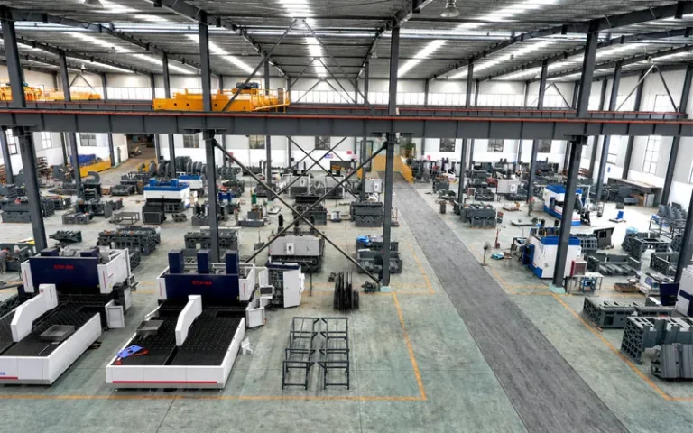
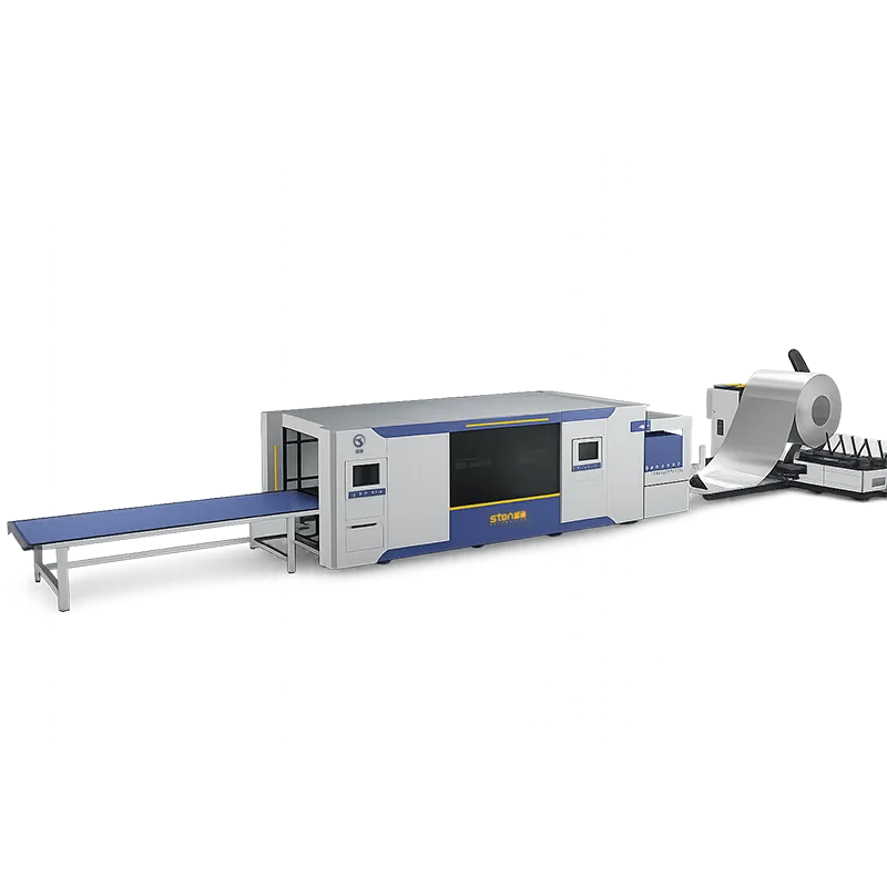
An автоматическая линия производства листового металла links uncoiling, leveling, laser cutting, punching, bending and stacking under one control system with automated transfer between stations. The difficult part is not the machines. It is synchronising a continuous coil process with discrete part handling, and buffering the stations so that one stoppage does not halt the line.
Three things get called “automatic,” and they cost differently
Before any process discussion, settle which of these you are buying. Suppliers rarely distinguish them and buyers rarely ask
- Automated machines, manual transfer. Each machine runs CNC programs without operator intervention during the cycle. Parts move between stations on carts or by forklift. Programming is per-machine. This is where most sheet metal factories already are.
- Linked cells. Two or three machines connected by robot or truss handling, with a shared part queue. A turret punch press with automatic loading, sheet separation, positioning, unloading and stacking is a Level 2 cell. So is a panel bender with a robotic arm. The cells still run as islands.
- A synchronised line. Coil to stacked part, with one control system managing process interconnection, scheduling and data traceability across all stations. STON supplies this as a customised line planned against the user’s product structure, capacity requirement, site layout and process flow.
The jump from Level 1 to Level 2 usually pays back on labour. The jump from Level 2 to Level 3 pays back on material utilisation, work-in-progress reduction and consistency, and it fails outright if your product mix is wrong. The last section of this article is about that.
Process one and two: uncoiling and leveling, where the line’s rhythm is set
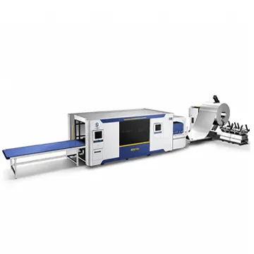
The uncoiler unwinds the strip coil and establishes a synchronous material balance with the leveler. Body and base are welded structures given heat aging treatment. Coil capacity is ≤10 T, with inner diameter φ508–630 mm ⁽¹⁾ and outer diameter φ1,000–1,600 mm.
Leveling is where the line either works or does not. STON’s leveling rollers are 40Cr, with self-aligning or needle roller bearings on the work rollers for load capacity and low friction. Different levelers are configured to the customer’s thickness and accuracy requirement. Published output: leveling accuracy ±1 mm/m², diagonal accuracy ≤1 mm/2000 mm.
Why this matters two stations downstream: a panel bender holds angle accuracy of approximately ±0.5°/m and straightness of about 0.2 mm/m. Those figures assume a flat blank. Residual coil set that survives the leveler shows up as angle scatter at the bender, and no amount of angle compensation recovers it reliably across a batch. Buyers who chase bending accuracy in the specification and accept a standard leveler have optimised the wrong station.
Material envelope, coil-fed line
| Параметр |
Value |
| Raw Material |
Cold-rolled sheet, galvanised sheet, stainless steel |
| Thickness |
0.5–2.0 mm (stainless steel ≤1.5 mm) |
| Plate Width |
1,000–1,500 mm ⁽²⁾ |
| Coil Weight |
≤10 T |
| Coil Inner / Outer Diameter |
φ508–630 mm ⁽¹⁾ / φ1,000–1,600 mm |
| Leveling Accuracy |
±1 mm/m² |
| Diagonal Accuracy |
≤1 mm/2,000 mm |
| Threading Speed |
5 m/min |
| Line Speed |
0–12 m/min, adjustable |
| Running Height |
+800 mm |
| Power Supply |
3φ AC 400 V ±5%, 50 Hz ±2% |
| Air |
0.5–0.6 MPa, 0.6 m³/min |
The line parameter table states φ508–630 mm; the company product overview states Ø470–630 mm. Both are reproduced. Confirm against your coil supplier’s mandrel before ordering. ⁽²⁾ The line parameter table states 1,000–1,500 mm; the product overview states 200–1,500 mm. Confirm the range for your configuration with STON engineering.
Process three: laser blanking, and the moment the line stops being continuous
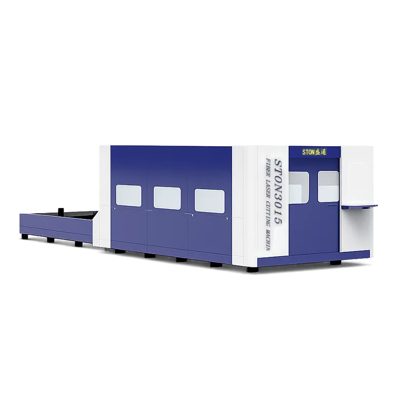
The fibre laser cutting section takes leveled strip and produces finished blanks with intelligent nesting. STON offers 1 kW to 6 kW, a PC industrial control computer with a graphical interface, compatibility with AutoCAD and CorelDraw files, and a cutting process parameter database with real-time parameter adjustment during the cut. Feeding uses a high-precision ground rack with servo control.
Here is the transition that defines line design. Uncoiling and leveling are continuous, speed-governed processes. Laser blanking is stop-start: feed a length, clamp, cut, release, feed again. Everything downstream is discrete: individual parts moving one at a time.
A line that pretends these are the same process runs badly. The three practical answers:
- Loop or festoon between leveler and laser. The leveler runs at constant speed into a loop; the laser draws from the loop in bursts. Loop depth sensors modulate leveler speed. This is the standard arrangement and the reason your line needs pit depth or overhead clearance in the layout drawing.
- Servo feed with stop-and-cut and no loop. Simpler and shorter, but the uncoiler and leveler now accelerate and decelerate with every sheet, which wears drives and degrades leveling consistency at the ends of each feed length.
- Cut-on-the-fly. Highest output, tightest control requirement, and only worthwhile on simple repeated contours.
Ask which one your quotation is based on. It changes the floor length, the pit requirement and the achievable line speed more than the laser power does.
For standalone or double-platform laser configurations, published footprints are 4,500 × 2,600 mm for a single-table 3015 and 9,000 × 3,100 mm for the exchange-table 3015, rising to 5,500 × 2,600 mm and 12,000 × 3,100 mm respectively at 4015. Power supply is three-phase 380 V/50 Hz, with total installed capacity ≤50 kVA at 3,000 W (60 kVA supply recommended) and ≤100 kVA at 6,000 W (120 kVA recommended). A dual-circuit chiller with digital temperature display cools two core locations independently and cuts in and out automatically against a setpoint.
Process four: turret punching with automatic loading and unloading
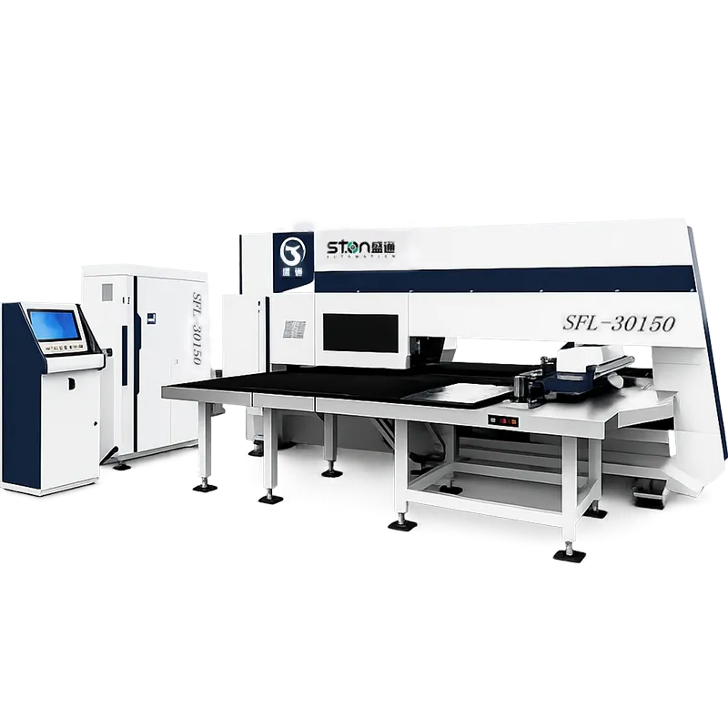
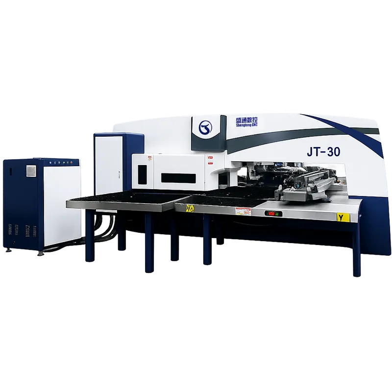
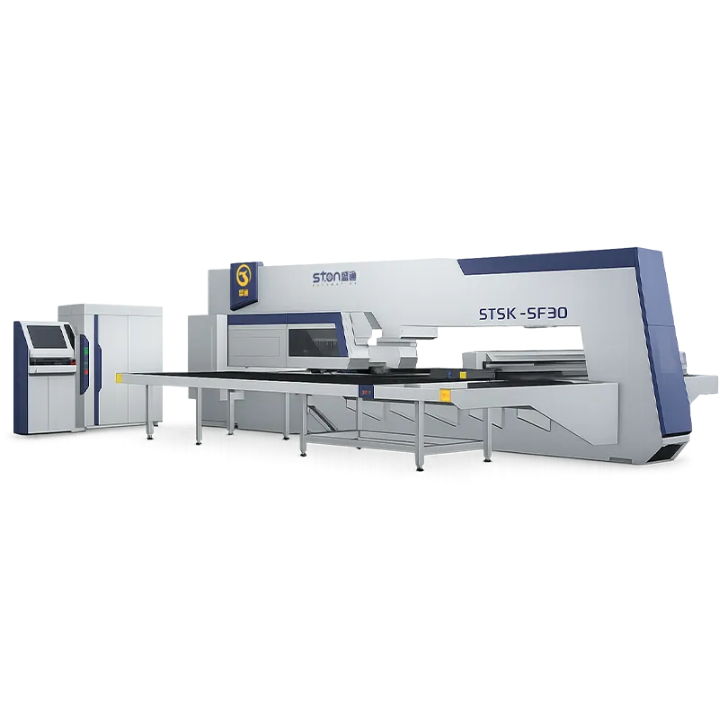
Punching, trimming, forming, louvering and rib pressing are what the laser cannot do, and on high hole counts the turret is faster per feature by a wide margin. STON’s line configuration runs the turret with an automatic loading and unloading unit so that loading, sheet separation, positioning, unloading and stacking are unmanned.
| Параметр |
SF Series (Servo) |
JT Series (Mechanical) |
| Максимальная скорость револьверной головки |
40 rpm |
30 rpm |
| Machining Accuracy |
±0.1 mm |
±0.1 mm |
| Maximum Load Capacity |
150 kg |
150 kg |
| Combined Power Consumption |
Approx. 3–5 kW |
≤2 kW |
| Air Source Pressure |
0.55 MPa |
0.55 MPa |
| Power Supply |
380 V ±5% |
380 V ±5% |
| External Dimensions |
5,200 × 5,000/5,500/6,500 × 2,230 mm |
5,200 × 5,000/5,500 × 2,100 mm |
Both use a brush plus omnidirectional steel ball composite tabletop, customisable to pure brush or pure steel ball. On pre-painted or brushed stainless parts this is a specification item, not a detail: pure steel ball tables mark soft coatings, pure brush tables drag on heavy blanks.
The mechanical JT carries a flywheel drive with over-tonnage protection that cuts impact power, triggers the safety pin or disengages the clutch when pressure exceeds the set value. Servo drive costs more in power draw and buys you programmable ram control. For a line running one thickness at high volume, mechanical is defensible. For a line switching between 0.8 mm and 2.0 mm, the servo’s stroke control earns its power bill.
Where the part genuinely needs punching and contour cutting in one clamping, the SFL punch-laser combined machine handles both: 300/400 kN (30/40 T) punching force, “O” type closed frame, X-axis 2,500 mm in one position and up to 5,000 mm with secondary positioning, Y-axis 1,250/1,500 mm, step pitch 405 times per minute at 5 mm, die layout of 16A / 11B / 3C / 2D including 1B and 1C rotary stations. A single CNC system controls punch, laser and axis motion together, with FANUC available as an option. STON states it occupies approximately 40% less floor space than a separate punch press plus laser cutter and removes the handling, re-clamping and re-alignment time between them.
Process five: bending, and the part where automation is hardest
Bending is where lines fail to reach rated output, because it is the only station whose cycle depends on part geometry rather than part size.
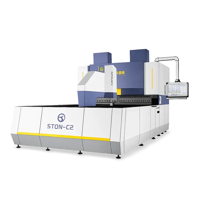
A CNC panel bender completes multi-angle bends on a panel in one clamping, with automatic feeding, positioning, bending and unloading, angle compensation, and rapid program switching between products.
| Model |
Max. Bending Size (mm) |
Max. Bending Height (mm) |
Max. Thickness at Full Bend |
Servo Axes |
External Dimensions (cm) |
| A (1000) Welded |
1,000 × 1,000 |
170 / 300 / 400 |
CR 1.5 / SS 1.0 |
15 |
425 × 160 × 255 |
| A+ (1200) Welded |
1,200 × 1,200 |
170 / 300 / 400 |
CR 1.5 / SS 1.0 |
15 |
430 × 180 × 255 |
| B (1400) Casting |
1,400 × 1,250 |
170 / 300 / 400 |
CR 2.0 / SS 1.2 |
15 |
450 × 206 × 290 |
| B+ (1600) Casting |
1,600 × 1,250 |
170 / 300 / 400 |
CR 2.0 / SS 1.2 |
15 |
462 × 226 × 290 |
| C (2000) Casting |
2,000 × 1,500 |
170 / 300 / 400 |
CR 2.0 / SS 1.2 |
15 |
558 × 270 × 310 |
| D (2500) Casting |
2,500 × 1,500 |
170 / 300 / 400 |
CR 2.0 / SS 1.2 |
15 |
615 × 308 × 310 |
| D+ (2800) Casting |
2,800 × 1,500 |
170 / 300 / 400 |
CR 2.0 / SS 1.2 |
15 |
630 × 338 × 310 |
Process limits common to the range: bending angle 0–180°; minimum bending height 5 mm; minimum inner dimension for four-sided forming 140 × 190 mm; minimum two-sided dimension approximately 140 mm; angle accuracy approximately ±0.5°/m; straightness approximately 0.2 mm/m; dimensional accuracy approximately ±0.1 mm/m; three-phase 380 V and 0.6 MPa air. Suction-cup type models cover the A to B+ range only.
Model designations appear as A / A+ / B / B+ / C / D / D+ in the product tables and as A2 / B2 / C2 / D2 / F2 on the official product page. A maximum bending length of 4,100 mm appears in company overview material against 2,800 mm in the model table, and a ±0.01 mm accuracy claim appears against the ±0.1 mm/m dimensional accuracy in the same table. The model table is treated as governing here. Request written confirmation of series naming, maximum length and accuracy basis on your quotation.
Three configuration decisions that determine whether the bending station keeps up:
- Frame material. Welded frames are rated CR 1.5 mm / SS 1.0 mm at full bend; cast frames CR 2.0 mm / SS 1.2 mm. Running 1.5 mm cold-rolled on a welded frame is operating at the published ceiling every cycle.
- Auxiliary knives. Upper, lower or both, in 42CrMo forged material, with customisable length for local short bends. Parts needing a short flange inside a long edge either get an auxiliary knife or leave the line for a press brake.
- Feeding method. Clamp type, C-axis lifting, magnetic grippers or suction cup assemblies, selected per workpiece in the pre-sales analysis. This is the single most common cause of a line running below rated output: the handling method suits the sample part and not the third SKU.
Where parts need arc bends, dead edges or offsets rather than simple flanges, the flexible edge bending machine covers 1200 / 1600 / 2000 sizes, maximum forming 2,000 × 1,500 mm, maximum bending height 100 mm, minimum four-side inner dimension 200 × 200 mm and minimum bending height 4 mm, with positive or positive-plus-negative bending. Its control system supports up to 25 axes of concurrent linkage.
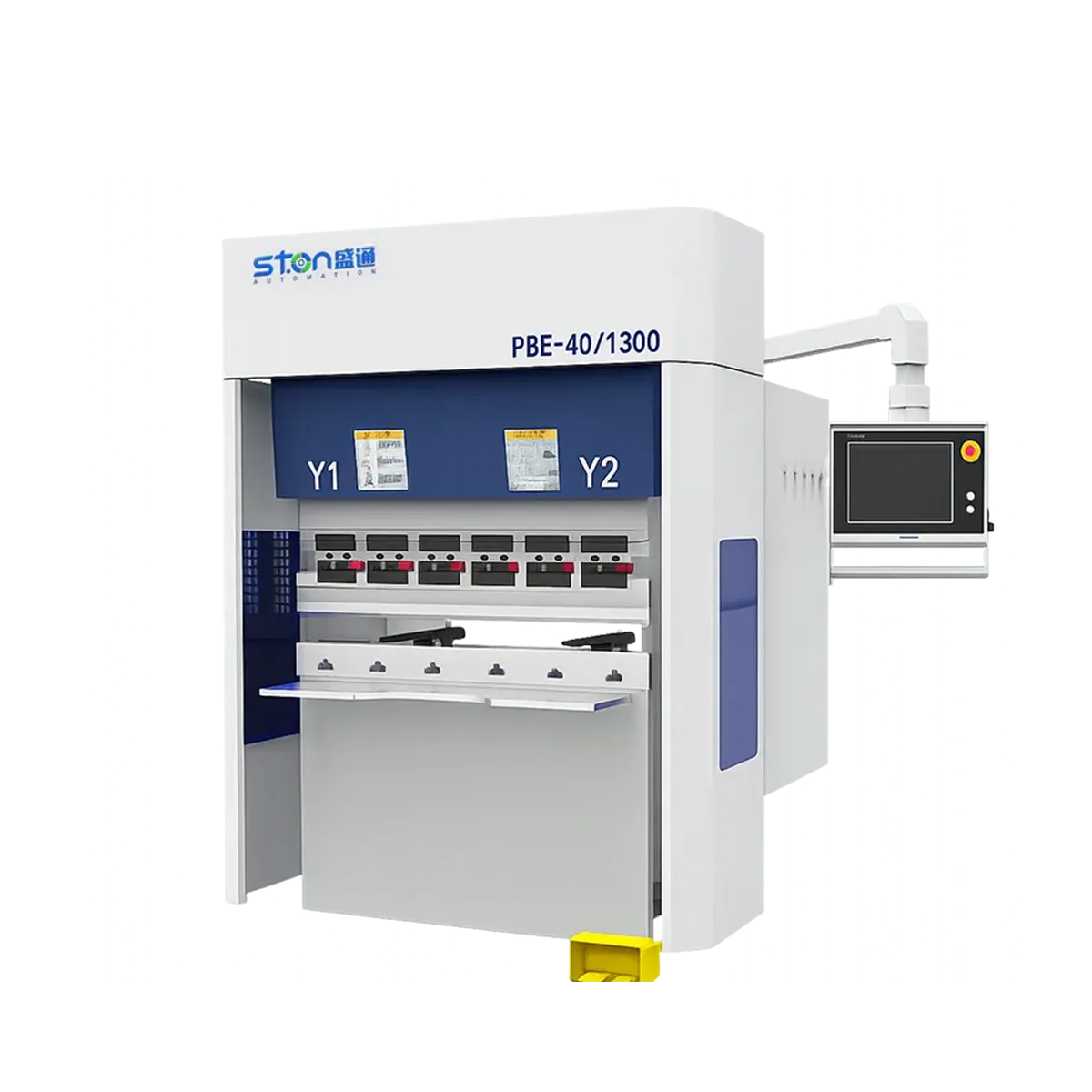
Heavy or out-of-envelope work still belongs on a press brake. STON’s electro-hydraulic range runs from 63 T/1500 mm to 320 T/4100 mm, with DELEM 53T, 58T, 66T or 69T controls or an Italian ESA option, mechanical crowning compensation, grating ruler closed-loop feedback and multi-axis CNC back gauge. The 100/3200 weighs 8,500 kg at 3,720 × 1,720 × 2,550 mm.
Process six and seven: welding and stacking
An automated welding workstation combines a welding robot, positioner, tooling fixtures and a seam tracking system for butt, fillet and spot welding. Adding it converts a parts line into a sub-assembly line, which changes your work-in-progress model entirely and is worth evaluating separately from the forming line.
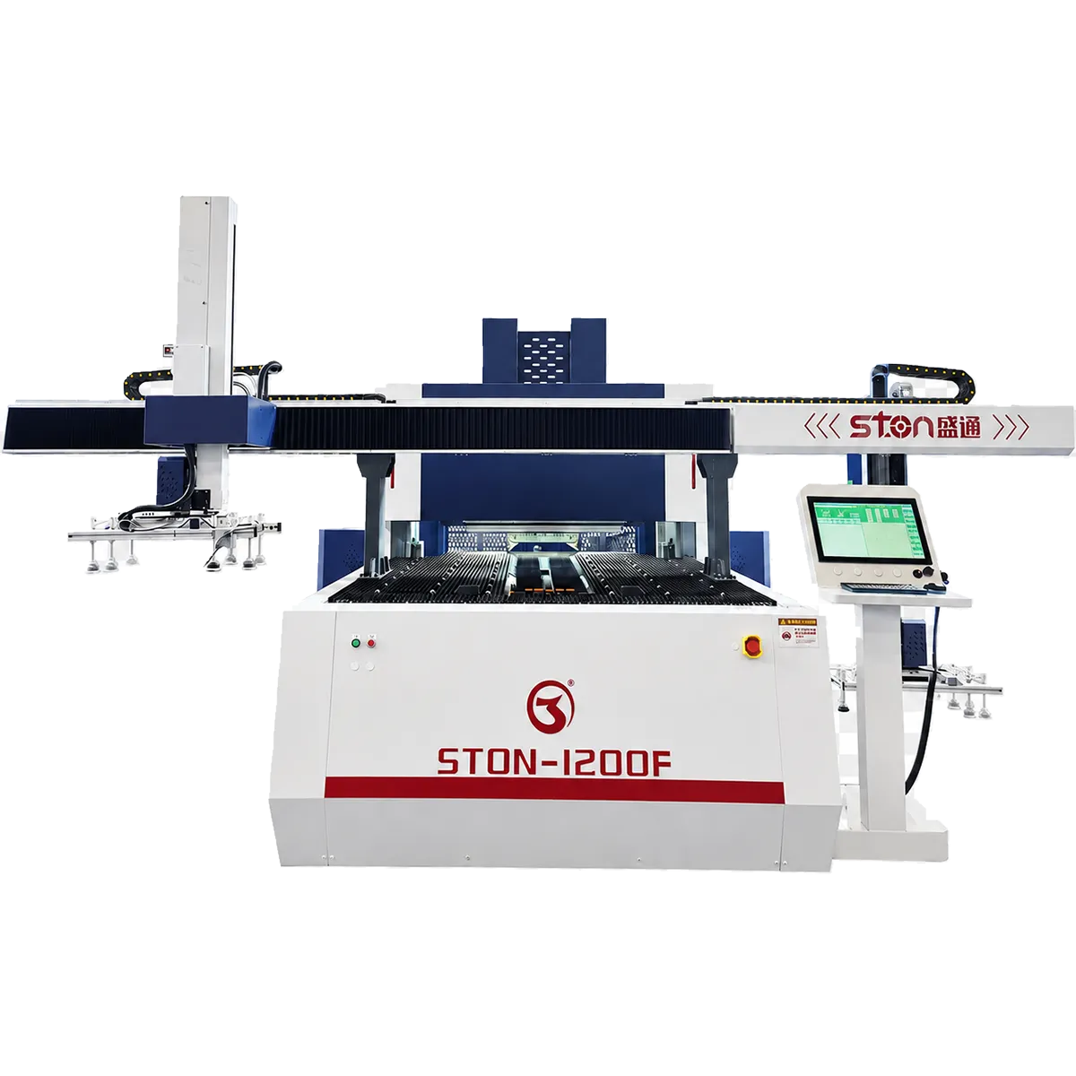
Loading, unloading and transfer across the whole line use robotic arms, gantry systems or truss-type manipulators. STON’s panel benders retain a native automatic loading and unloading docking port compatible with most robotic arm and gantry brands on the market, which matters if you already run a preferred robot brand or intend to standardise later.
The control layer: what actually synchronises the line
This is where published material across the category thins out to phrases about real-time monitoring and coordinated data flow. Here is what to specify instead.
One control system, or several talking to each other. STON’s fully customised lines use a unified control system supporting process interconnection, intelligent scheduling and data traceability. Individual machines run their own controls: the turret uses a Windows platform with RTEX bus servo units, with FANUC, Siemens or Rexroth available on request; the panel bender uses an imported all-electric servo closed-loop system with bus control and multi-axis concurrent linkage across 15 axes. Ask explicitly whether your line is one system with station modules, or several systems exchanging I/O. Both work. They differ enormously in how you diagnose a fault at 2 a.m.
The handshake list. Request the signal list between every adjacent pair of stations before contract signature. At minimum it should contain: part-present at pickup, ready-to-receive at the downstream station, program ID passed with the part, cycle-complete, fault class and severity, and the stop propagation rule for each fault class. A supplier who cannot produce this list has not designed the integration yet.
Fault propagation policy. Decide, per fault, whether the line stops, the station stops and the buffer drains, or the part is flagged and passed. A jam at the stacker should not stop the uncoiler. An out-of-tolerance leveling reading should stop everything, because it is producing scrap upstream of three stations.
Program flow. A part program exists in the nesting software, the laser control, the turret control and the bender control. Confirm which system is the master and how a revision propagates. Factories that revise a bend program at the machine and not in the master file lose the traceability they paid for within a month.
Traceability output. Ask what the line records per part or per batch, in what format, and whether it can be exported to your ERP or MES. Data traceability written on a specification sheet and data you can actually query are different products.
Safety and stop architecture for a linked line
Machinery linked to function as a whole is treated as an assembly of machinery under Machinery Directive 2006/42/EC, with Regulation (EU) 2023/1230 now governing new placements on the EU market. That means the line as installed carries its own risk assessment, technical file and Declaration of Conformity, not just a folder of certificates for the individual stations.
Specific to line integration, request:
- Risk assessment to EN ISO 12100 covering the interfaces between stations, particularly the transfer and buffer zones where operators actually reach in
- Safety functions rated to EN ISO 13849-1 with the performance level and category stated per function, including cross-station stop propagation and restart interlocking
- A safety zoning drawing showing which E-stop stops which stations, and where a zone can be entered while adjacent zones keep running
- Muting and restart logic for material entry points, which is where coil lines carry their highest-energy hazards
- Conformity to EN 12622 and EN ISO 16092 for any press brake within or adjacent to the line
STON’s machines carry ISO and CE certification, with laser protection devices that monitor the guarded area in real time and stop the machine on intrusion, over-tonnage protection on the mechanical turret, and fully enclosed rear guarding on the flexible edge bending machines. Manufacturing runs in-house across a 20,000 ㎡ factory covering casting, heat treatment, machining, welding, assembly and inspection, with a published ±0.05 mm assembly accuracy and ISO 9001 certification.
Часто задаваемые вопросы
Q: How is line availability different from machine availability?
A: Machine availability is a single machine’s uptime. Line availability, for rigidly coupled stations, is the product of them all — five machines at 95% give 77.4% at the line. Buffers break the coupling and pull line availability back toward the worst single station. Always ask a supplier which figure their throughput claim is based on.
Q: Can one line handle both punching-heavy and cutting-heavy parts?
A: Yes, but not efficiently in a single series flow. A series line optimised for cutting-heavy parts leaves the turret at low utilisation, and vice versa. Either split the flow into parallel branches from a shared buffer, or specify a punch-laser combined machine so both operations share one clamping.
Q: What is the minimum part size the line can handle?
A: On the panel bender, four-sided forming needs a minimum inner dimension of 140 × 190 mm, two-sided forming approximately 140 mm, and minimum bending height 5 mm. The flexible edge bending machine’s minimum four-side inner dimension is 200 × 200 mm with a 4 mm minimum bending height. Small parts below these limits need dedicated micro-part configuration, which STON handles as a customisation rather than a standard option.
Q: Do I need to buy the whole line at once?
A: No, and staging is often better. A common sequence is to install the bending cell with automated loading first, since it usually carries the largest labour content, then add the blanking front end once the part programs and operator skills are established. Confirm at the outset that the control architecture supports later expansion, and that docking ports and I/O capacity are specified for the full line even if only part of it is delivered.
Q: How many people run a synchronised line?
A: Typically one operator at the HMI, one on coil handling and crane work, and one on unloading and stacking, with programming and maintenance shared. The count matters less than the skill shift: you replace several semi-skilled positions with fewer positions and one genuinely skilled programmer. Train two, not one.
Q: What does the line record, and can I get the data out?
A: STON’s customised lines are specified with data traceability under a unified control system. What the data contains, at what granularity, in what format, and whether it exports to your MES are separate questions that need answering in the contract. Ask for a sample export file during evaluation.
Q: How long from contract to rated output?
A: Request four separate figures rather than one: manufacturing, shipping, installation and commissioning, and ramp to rated output. The fourth is usually omitted from proposals and is the one that determines when you can sell the new capacity.



 11 августа 2026 г.